Internship report (Part 1)
Amul Milk Chilling Plant
Introduction
Milk chilling plants play an important role in the dairy supply chain by maintaining milk quality and safety immediately after milking. Positioned close to farms, they allow producers to quickly cool and store their milk under hygienic conditions, dramatically reducing bacterial infestation and spoiling of the milk. By combining milk from multiple small communities in villages, these facilities ensure consistent batch quality, facilitate routine testing for fat content and contaminants, and enable fair pricing based on standardized measurements for producers and chilling and quality control for dairy firms.
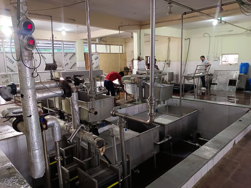
The milk chilling plant I interned at employed the following process:
- Gaseous ammonia was compressed and heated using a compressor
- It went through an oil separator to remove the compressor oil impurities
- The ammonia was then turned into liquid form using an open liquid waterfall condenser on the roof of the plant
- The ammonia then rapidly cooled after it passed through an expansion valve where it entered the Ice-Brine tank (IBT)
- In the IBT, the ammonia came in contact with the brine and cooled it
- The brine was output from the IBT and input towards the plate heat exchanger (PHE)
- Meanwhile room temperature milk was also being input to the PHE
- The brine and ammonia are recycled
- The cooled milk is stored and exported at the end of the three hour cyclical process

After I thoroughly understood this process, I was tasked with 3 objectives:
- Objective 1: What is the difference between the observed and the actual temperature of the PHE output brine, if a constant inlet and outlet temperature is assumed?
- Objective 2: Similarly calculate the IBT, compressor inlet ammonia, and IBT exit ammonia temperature
- Objective 3: Would insulation on the pipes be economically worth their cost?
The first part of this report will cover the process of the plant(as shown above) and the first objective whereas part 2 will focus on the 2nd and 3rd objectives

- Objective 1
To calculate the theoretical PHE outlet brine temperature and compare it to the actual we would firstly require the mass flow rate ratio of the milk to the brine. To obtain that value the calculations are as follows
(The reason why we take in – out for milk whereas out – in for brine is that ∆𝑡 is being kept consistent as hot – cold to get a positive mass flow rate ratio.)
The specific heat capacity of milk is 3.93 kJ/kg◦C Output milk temperature = 6.0◦C
The specific heat capacity of brine is 2.7 kJ/kg◦C Input brine temperature = -8.3◦C
Input temperature of milk is 32.1◦C Recorded brine output temperature= 2.7◦C
Using these values we can use a rearranged version of the 𝑄 = 𝑚𝑐∆𝑡 formula to calculate the theoretical output temperature of brine (t2,out) for different fixed values of the inlet milk temperature, outlet milk temperature, and inlet brine temperature and then compare these values with the actual outlet value of the outlet brine temperature at those conditions. A sample calculation which will be repeated for the different readings is shown below:
For inlet milk = 30◦C, outlet milk = 5◦C, inlet brine = -12.2◦C

Objective 1 conclusion
The table below records the measured input and output brine and milk temperatures and compares it to the theoretically calculated brine outlet temperature
As we can observe from the table the theoretical and actual values of the outlet brine temperature significantly deviate at the beginning and gradually converge with time. The reason for this is:
- Initially all the pipes, IBT walls and PHE metal are at ambient Therefore a higher amount of energy is lost in cooling this equipment as the brine loop begins.
- The actual brine temperature decreases with time since the ambient temperature equipment heat loss reduces with. However, the theoretical brine temperature(which ignores this energy loss) rises with time because of the rise of the inlet brine temperature during the initial stages which occurs due to warming by milk and time taken by the compressor to reach full power.